 

3D Scanning

Background

As of October 2018 I have about 6 months of 3D scanning under my belt. I feel that is enough confidence to start advertising my services.  A huge portion of my business is manufacturing parts to fit other parts.  Usually things aviation related like a wingtip to fit a particular wing or an instrument panel to fit inside a cockpit.  It has been a rather steep learning curve but I am now producing scans that are extremely accurate for the work I do so I have decided to market my services.

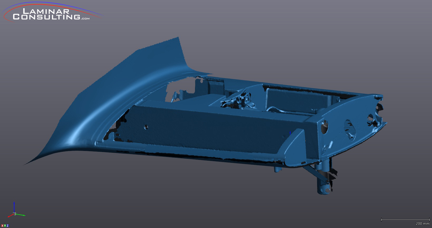
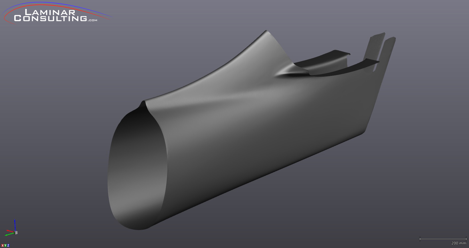
The primary goal of my scanning ability was to be able to scan larger than normal parts.  Most of what I do is big when compared to average 3D scanning.  A lot of companies can scan things that fit on your desk.   When I searched for this service locally here in Kansas City I was unable to find anyone with the capability to scan objects as large as my projects are.  For that reason I took it upon myself to fill the void.

Solution

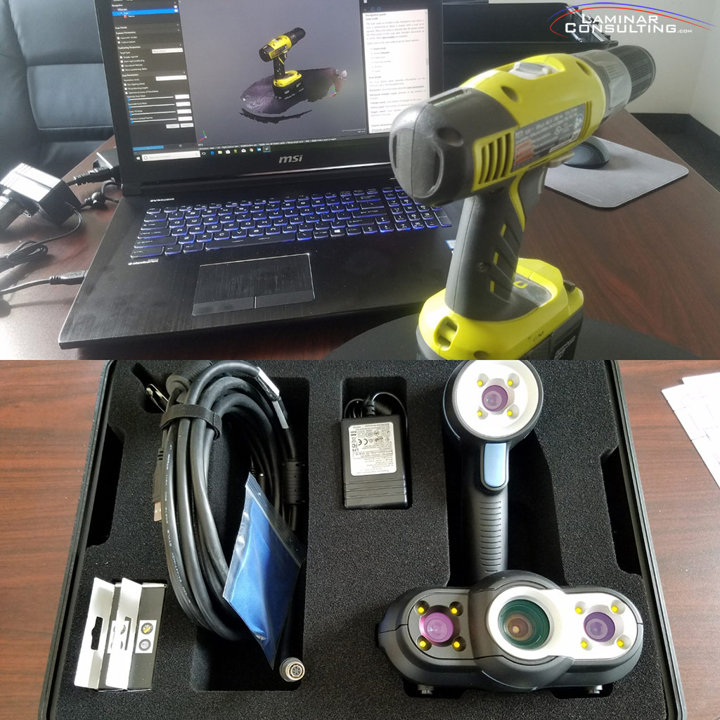
Some of the goals I had for this phase of my business included capturing geometry that would often times be hard to scan.  Something as simple as pencil marks on a mold would not show up on most scanners available on the market.  When I discovered the option to include color, or basically overlay images as a texture, that solved a lot of issues for me.  This photo was the first thing I scanned when I took the scanner out of the box.  Pretty amazing.

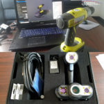
Another key requirement was the ability to be extremely mobile.  Obviously most of the time I have to travel to the airplane/thing I’m working on, rather than it come to me.  Therefore having a scanner that easily travel with very low requirements was essential.  Basically all I need is power, my laptop and the scanner.  I even have a small portable 1000w generator that can travel with me to in extremely remote conditions, when needed.

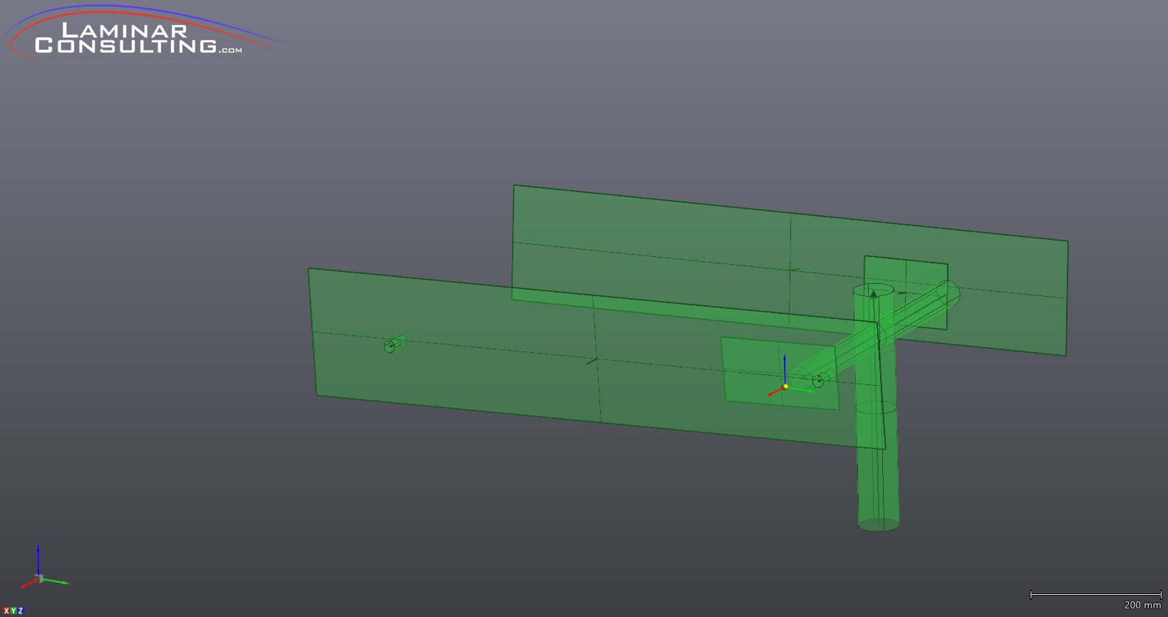
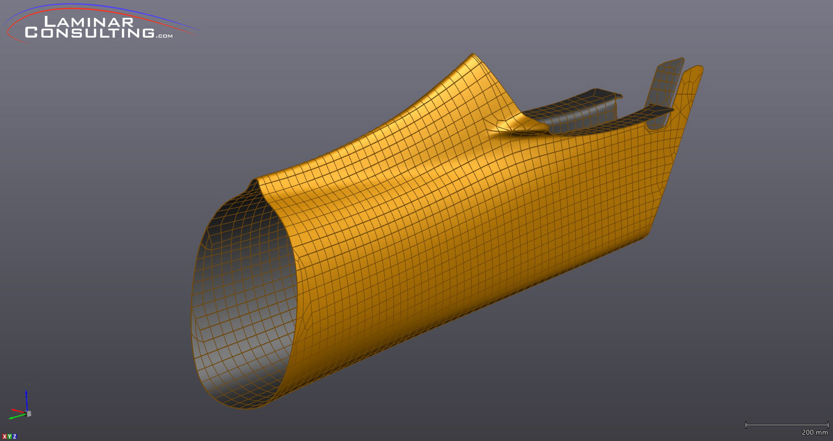
What I quickly discovered speaking with other commercial scanning services was that all they provided was the raw scan mesh itself.  That doesn’t make it totally worthless, but it seriously cuts down on the scans value as most of the CAD platforms have less than ideal tools to identify entities from the mesh.  For example, labeling a tube as a cylinder with a known dimension, or creating a surface that can be edited from the mesh.  These would all be requirements for me so I’m sure they are very useful things customers would request as well.

Examples

The image below is a prime example of the requirement to extract known entities from the raw scan data.  This landing gear assembly was scanned while installed in the stub wing on this Lancair Legacy.  Once the area had been scanned needed entities were located and created inside the native scanning software.  Working planes for the front and rear spars, wing attach fittings and the gear leg itself have all been identified and exported to CAD.

When dealing with large parts the most common way to work with that part in CAD is to use a surface.  This works well for most of what I generally scan.  Cowlings, fuselage parts, wings, tails etc.  It would also make sense for any organic shaped object like a bumper on a car or fairing for anything.

The image below shows the raw mesh converted to a surface which can then be edited in CAD.  The surface can be manipulated many ways to define patch density, tolerance to the scan, edge editing and more.  This makes any scan of a large part very useful to the end user.

The specifications of the scanner are listed here.  This is not a laser scanner, it uses white LED lights to map the surface.  This does create a few pros and cons regarding the object you are wanting to scan.

The Good

  • Very fast scanning.  It is possible to do something the size of a car in a single session.
  • Scan in color.  Great for reference marks or transfer of entities which don’t have any geometry.
  • Export in basically any format including direct transfer to SolidWorks and Inventor part files.
The Bad

  • Large part files take time to edit.  What can be scanned in an hour takes 3 hours to edit.
  • Glossy parts are difficult to scan due to reflections.  Dull white is the optimum surface finish.
  • Gloss Black is nearly impossible, but I’ve made it work with a few tricks.
SpecificationValue
AccuracyUp to 0.100 mm (0.004 in.)
Volumetric accuracy0.300 mm/m (0.0036 in./ft)
Resolution0.500 mm (0.020 in.)
Scanning area380 x 380 mm
(15 in. x 15 in.)
Stand-off distance400 mm (15.75 in.)
Depth of field250 mm (10 in.)
Part size range
(recommended)
0.3 – 3.0 m (1 – 10 ft)
Output formats.dae, .fbx, .ma, .obj, .ply, .stl, .txt, .wrl, .x3d, .x3dz, .zpr

Cost

Obviously the first question customers asks is “What is this going cost?”  The cost can vary greatly depending on how much editing of the scan is required, what entities need to be defined (if any), the file formats requested, etc etc.  There is no way to put a blanket cost on all common objects because none of the requirements are the same.

Please use the Contact form on this website to request a quote for your 3D scanning project and I’ll do my best to give you an accurate estimate.  I’m aware of many ‘hobbyist’ scanners that can be used for very little cost and I’ve taken many questions comparing my capability to those.  Let me put it this way, it isn’t even the same sport, let alone in the same ballpark.  The scanner I have costs more than an average new car, but to be honest a huge portion of that value is in the post scan editing capability that is completely unmatched in this industry as I know it.  Many places share pretty photos of scans, which I can do too, but few show the results of the scan used to actually create something.  I hope that makes sense.