 

Rapid Prototype Tooling

CAD to Low Production Mold - Fast

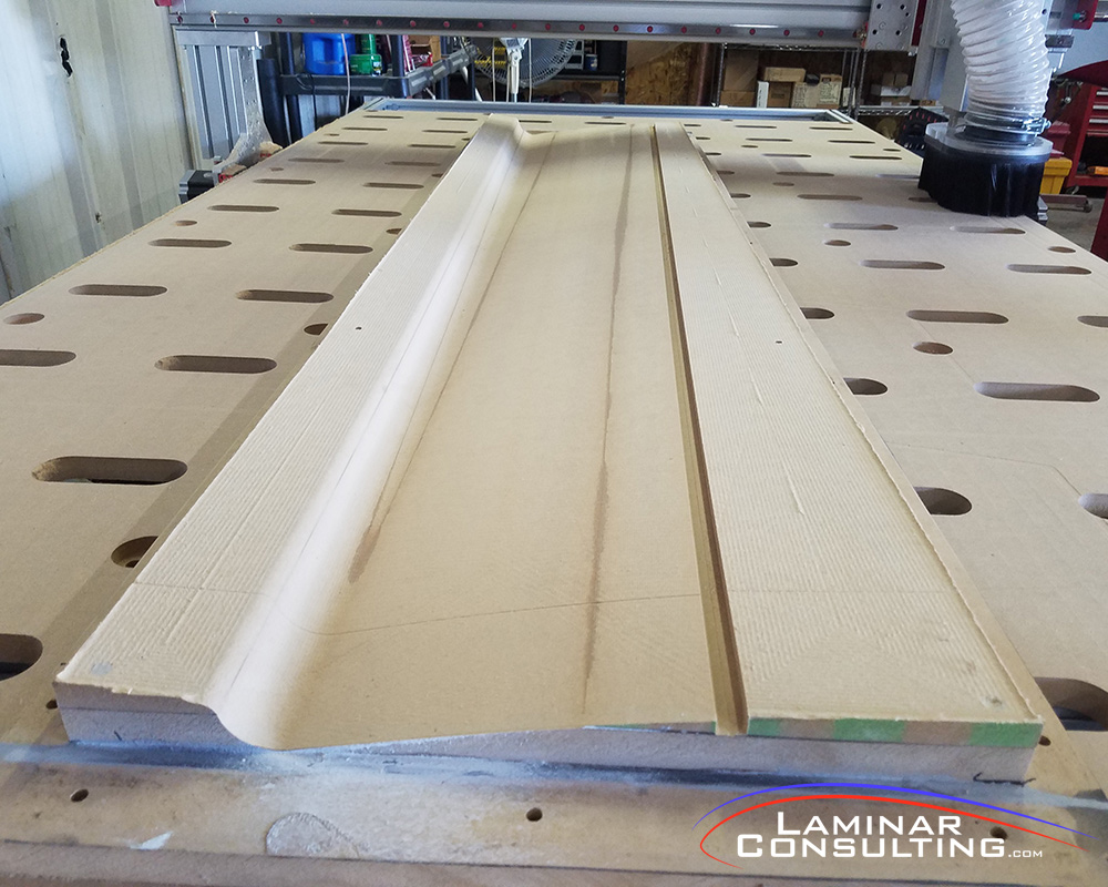
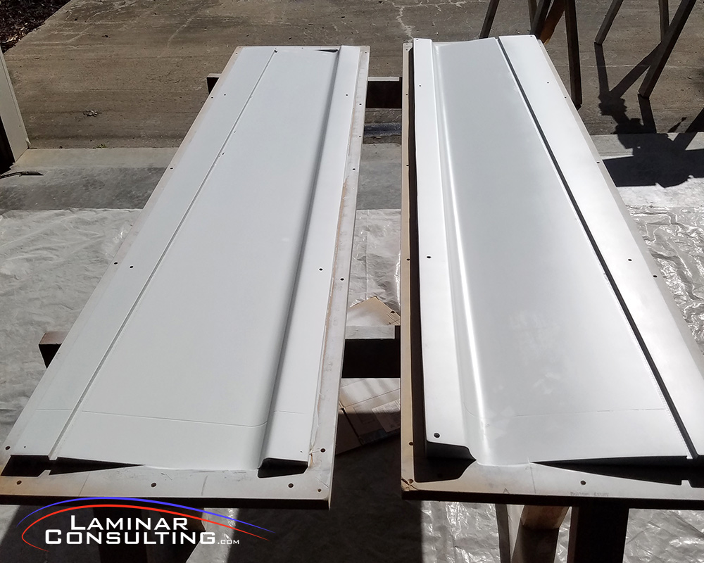
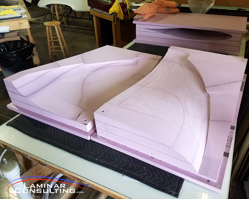
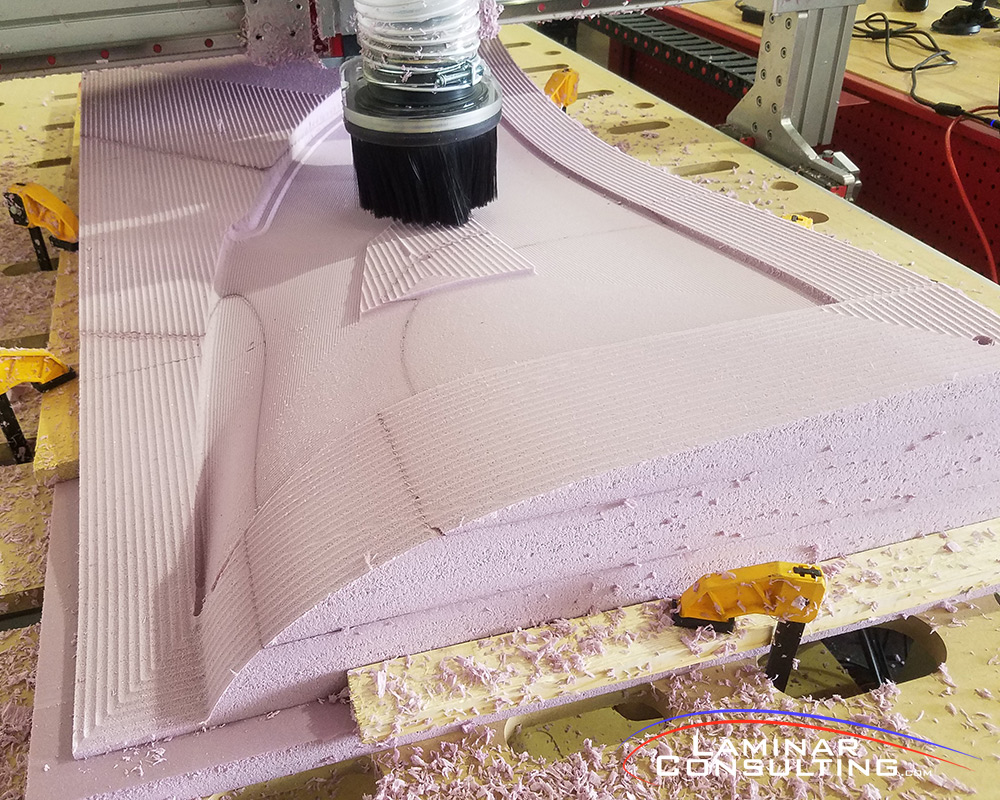
An often undesirable trait of working with composites is sanding, or bodywork in general, to create the surfaces we enjoy.  Ask any RV builder and they will almost all say the fiberglass portion of their build was one of the more difficult parts.  Actually I’m the opposite.  If I have to rivet more than 10 rivets in a row, I’m doing something wrong..

My usual response to those who dislike composites and often say “I hate all that sanding” is rather simple: I sand because I can generate a surface, compound in nature, that is far superior than any aluminum skin.  At the same time, if I were ok with dimples all over, I don’t have to sand it, and it could be as good as any RV.  I prefer better.

Early on I realized that to aid in the construction process and reduce build time, the parts quality makes the biggest difference in labor hours required to complete something.  The better the molds, the better the part, the less bodywork required to finish it.  One of the best ways to make tooling that is accurate is to start in CAD.  I spent a year and a half in night school getting my computer aided drafting certificate in AutoCAD, Inventor and Solidworks.  Now with the skill to generate the parts, I had to get them into real life.

Most experimental airplane parts are rather large, so I built a large format CNC machine capable of producing tooling that is accurate enough for my needs, +/- 0.001  The working area is 4′ x 8′ x 8″.  Larger parts are possible with tool indexing or machining in layers.  This has given me a great solution to bring parts from CAD to reality really quickly and accurately.

CNC Composite Tooling

The difficult part about fabricating composites is the requirement for a mold.  Molds come in many forms but are generally driven by their desired part purpose and complexity.  I’d say the most important force is the number of parts you wish for the mold to create.  Often what I deal with, prototypes, that number is very low if not one.  This leads me to avoid the high cost of what I call a more permanent mold and favor that of a not-so-permanent mold that can serve the purpose only once or twice.  Usually this is made from a foam or some sort of wood.

The low cost and easy machining properties of foam make that a very desirable choice when dealing with prototypes.  The downside being its relatively delicate surface seriously limiting the number of parts that can be produced.  When using something like MDF your costs go up slightly due to the increased material cost, increased machining time and later the surface preparation required to make a part.  But, again you are going from CAD direct to a female mold, skipping the entire plug and mold creation process.

CNC Cut Carbon Fiber-Foam Core Structures

A common area of structures that is often overlooked, CAD wise, is the ability to CNC what goes inside.  The outer shape is often the focus, but if the proper time is spent designing what goes inside, the results are a more accurate outer shape due to the perfect alignment inside.

I started designing ribs and spars from the CAD model and then cutting those parts from flat stock I also produce.  The results were fantastic and far superior to hand trimming parts to fit.  This also makes serial production much more efficient.  Why not go further?

Quickly I realized I spent a large about of time locating hard points and drilling for nut plates.  Why not pull that data from CAD too!  Now I CNC drill parts, say a spar for example, for all of the hardware attachments.  The accuracy is far superior then I could have ever measured by hand.